
Inventor Frame Analysis is an advanced analysis technique designed for optimizing the structure of frames used in various industrial contexts. The Autodesk Inventor software allows for the implementation of this system.
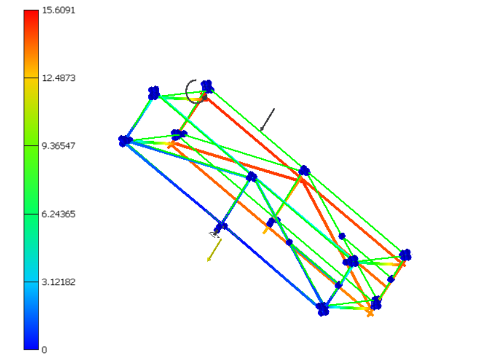
Image 0‑1: Frame analysis with IFA
Applications of IFA
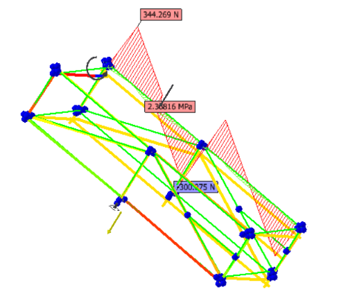
Image 0‑2: Visualization of load diagram (IFA)
The IFA provides a comprehensive overview of the mechanical stresses acting on a frame, allowing for the identification of critical points and the implementation of necessary corrections before the production phase. The program enables the input of specific data such as material types and load conditions, allowing for the implementation of customized simulations to adapt to project needs. Given these considerations, the program is particularly relevant for the design of:
- Industrial machinery
- Construction and building projects
- Automotive sector
- Naval industry
Differences between Inventor Frame Analysis and FEM analysis
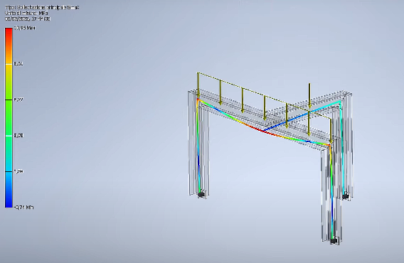
Figura 0‑3: IFA Analysis
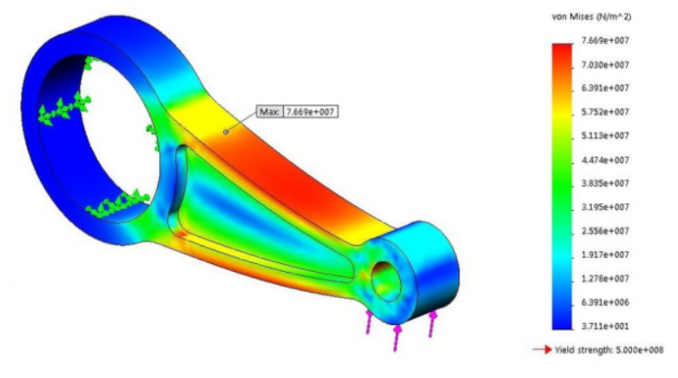
Figura 0‑4: FEM Analysis
The IFA and FEM analyses perform very similar tasks, so it is appropriate to highlight the differences between the two methods to better assess which analysis tool to use based on the study’s objectives.
- Analysis Methodology: While IFA primarily focuses on evaluating frames and structures, FEM analysis is a more general method that can be used to analyze complex systems with finite elements.
- Simplicity vs Complexity: IFA is designed for a quick assessment and optimization of frames, offering a simpler and more direct approach. On the other hand, FEM analysis can be used to meticulously analyze complex structures and systems.
- Focus on Frame Design: While both methodologies deal with structural analysis, IFA is specifically focused on frame design, providing tools and functionalities tailored to this purpose.
In conclusion, Inventor Frame Analysis (IFA) represents a powerful tool for structural design and offers numerous advantages, such as efficiency, design optimization, and the ability to design sustainably.
Although FEM analysis is a more versatile and complex technology, IFA stands out for its simplicity, intuitive interface, and integration into the Autodesk Inventor design ecosystem. Both IFA and FEM analysis play a crucial role in realizing innovative and reliable solutions for the future of the industry and engineering.
Edoardo Brienza
INVENTOR TUTORIAL : IFA ANALYSIS
-IFA Analysis of a frame on Autodesk Inventor Professional 2021
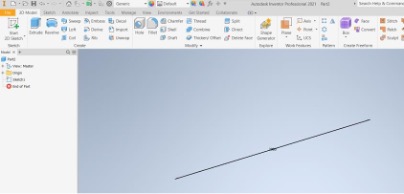
Step zero: Creating a frame on Inventor.
In Inventor libraries, models of beams and tubes are available. In this case, I want to create a W-section beam.
The first step is to create a base on ‘Part’ to define the length of the beam.
Then, simply copy the part into an ‘assembly’ file and use the ‘insert frame’ command.
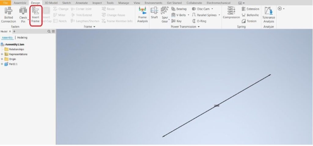
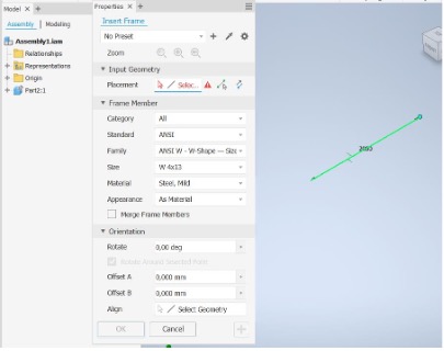
Select the Geometry input.
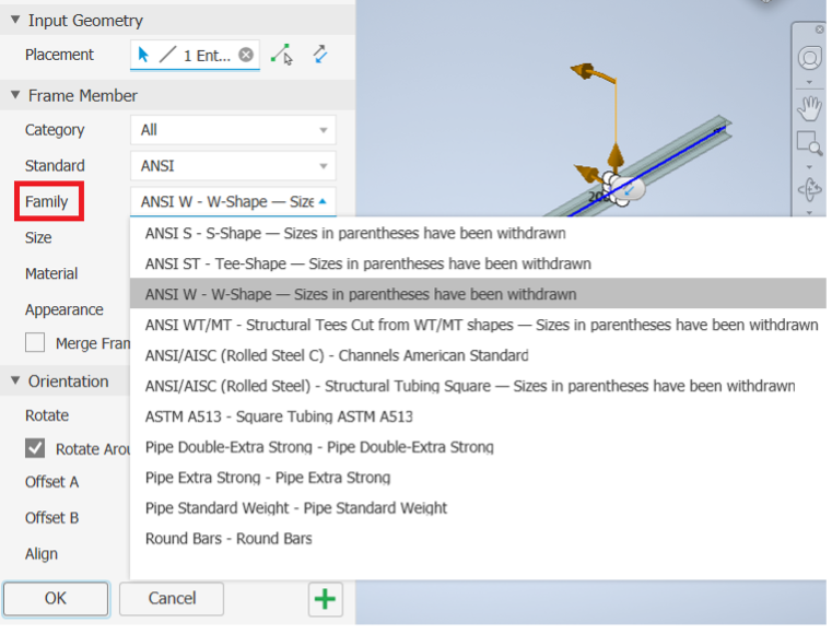
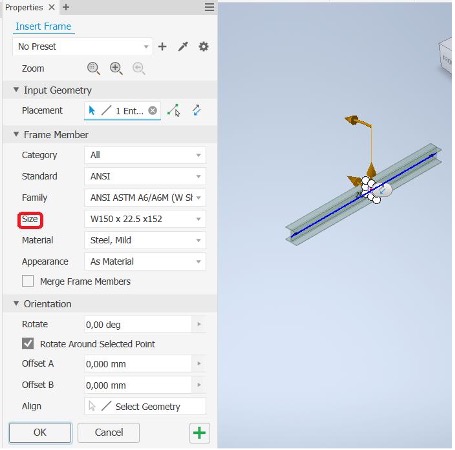
In the “family” section, you can choose the type of shape to select, and in “size”, the dimensions.
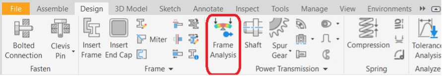
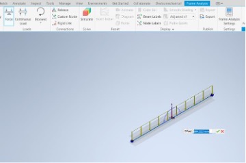
First step: Launching IFA.
The advantage of IFA analysis is much lighter than FEM analysis, allowing for the creation of a more complex structure and faster force analysis. As there is no mesh, the deformation of the beam cannot be visualized, but the theoretical line of deformation of the beam will be represented. Therefore, the IFA method is recommended for a preliminary analysis of the structure to immediately visualize errors or inconsistencies and then proceed to an FEM analysis.
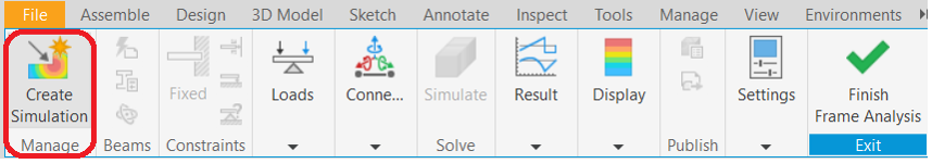

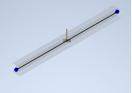
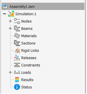
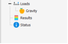
Inventor automatically inserts nodes and other relevant values, including a preliminary load which is gravity.
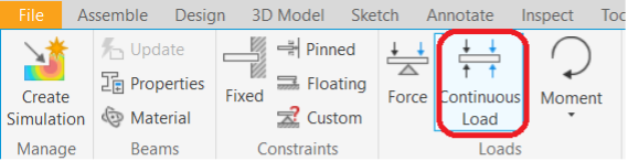
Second step: Application of loads and constraints.
Application of a distributed load.
After selecting the beam, the force distribution will appear on the screen.
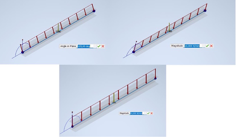
From here, we can set the intensity and direction of the loads. To insert a single force, just follow the same procedure described in the article related to FEM analysis, the only difference being that in IFA analysis, you can input the offset. If you try to start the simulation without defining the constraints, the following message will appear on the screen:
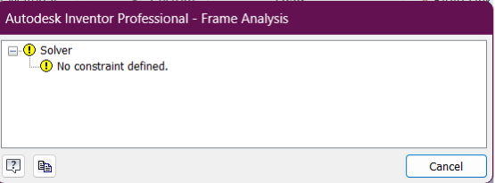
To define them, you need to select the following command:
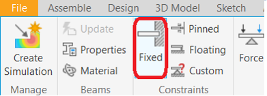
To set the constraints, it will be necessary to input the origin and the fixing point of the constraint in relation to the origin point.
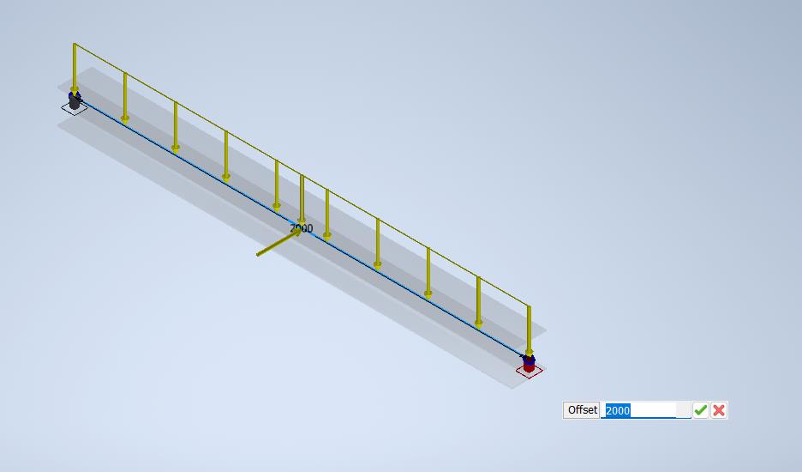
The constraints will appear on screen, symbolized by this element:
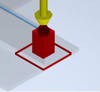
They won’t have any impact from a structural point of view.
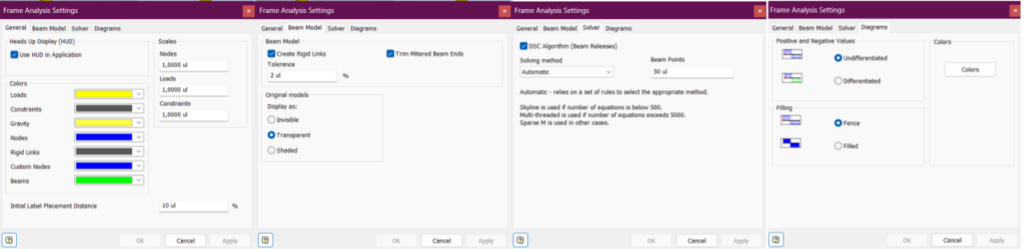
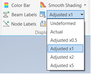
Third step: IFA settings
Here, it will be possible to modify the design of the output charts.

Fourth step: simulation
Once the constraints and forces are set, you can start the simulation.
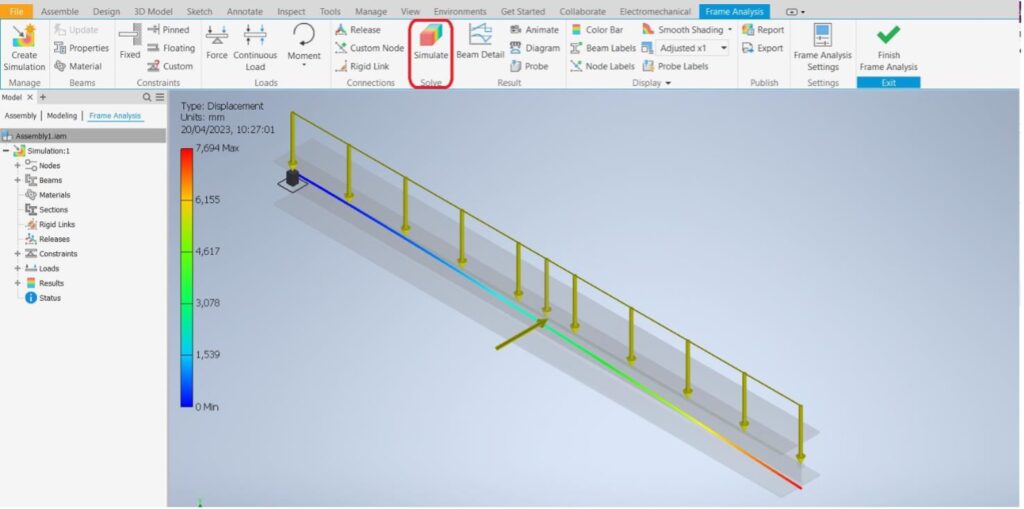
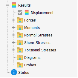
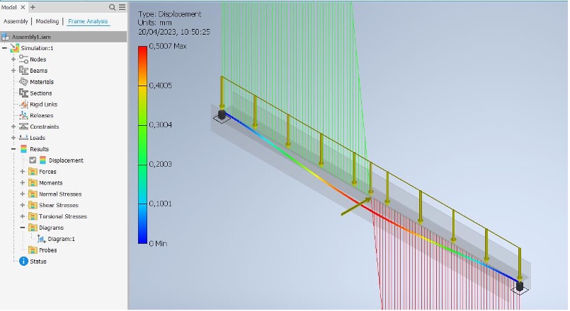
In the dropdown menu on the left, you can observe the simulation results.
In the visualization, you can immediately observe many values.
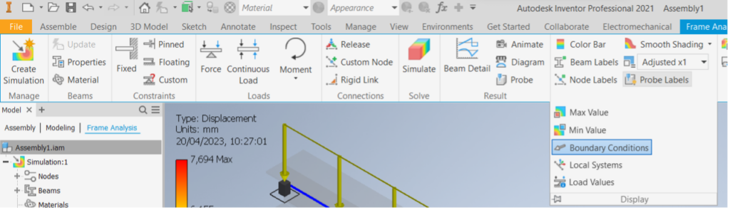
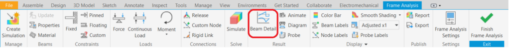
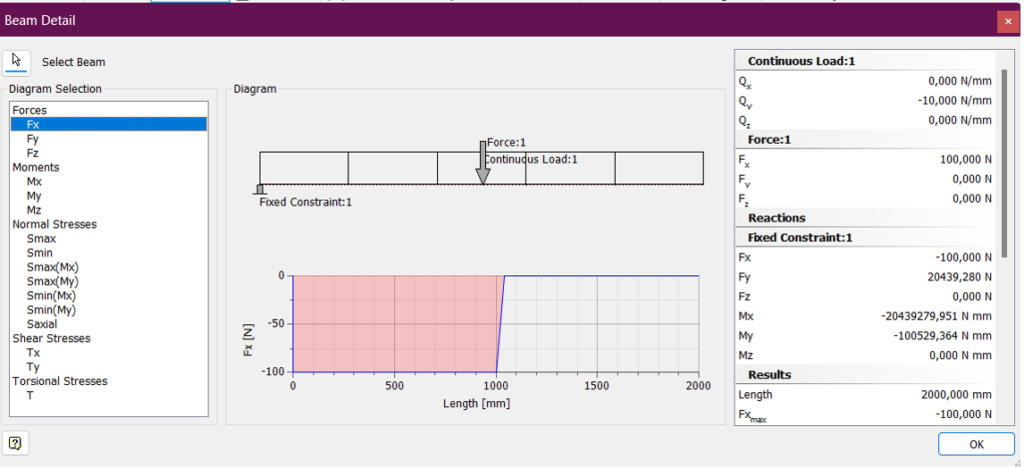
It is possible to enhance the graphics from the settings to view them more clearly. For a better view of the charts, simply select the ‘beam detail’ command. This will prompt you to choose the beam for detailed analysis.
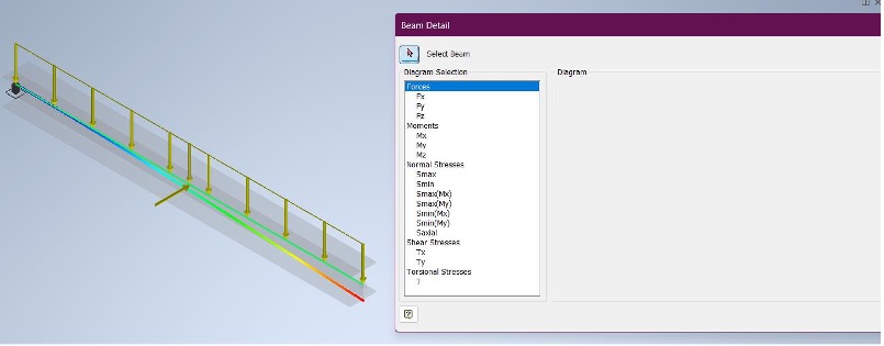
Now it will be possible to view in detail the various values of force, moments, and stresses.
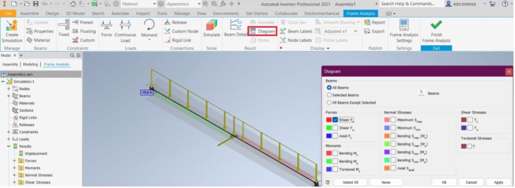
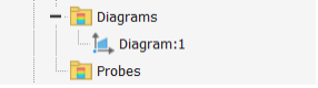
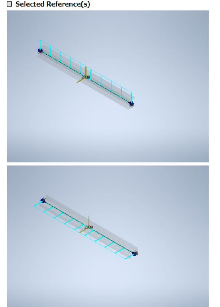
You can observe the charts in another way through the ‘diagram’ function, which allows the visualization of the graphs directly on a single beam or on the entire frame under study. The different diagrams created will be inserted in the dropdown menu on the left. The advantage of this analysis mode is the fastest way of changing settings; in fact, if you change the orientation of the beam:
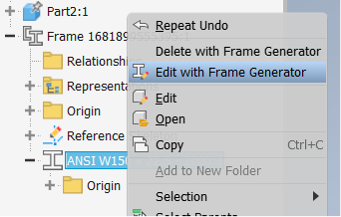
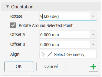
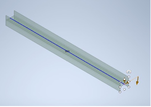
And rerun the IFA analysis.
It is noticed that all the previous settings have been retained.
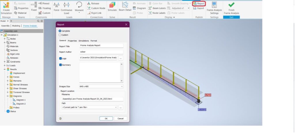
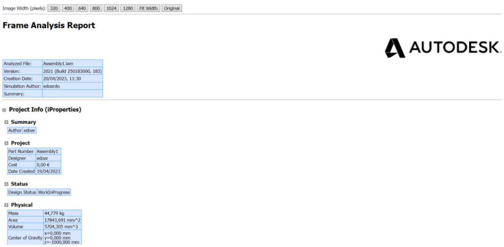
Seventh step: Report
Once the FEM analysis is complete, it is possible to create a separate file where various information from the analysis is automatically included.
ADDITIONAL INFORMATIONVarious pre-made components can be found on ‘traceparts’ (https://www.traceparts.com/it). Registration is free and provides access to a large library. Once the desired component is selected, simply choose ‘Inventor’ and proceed with the download.
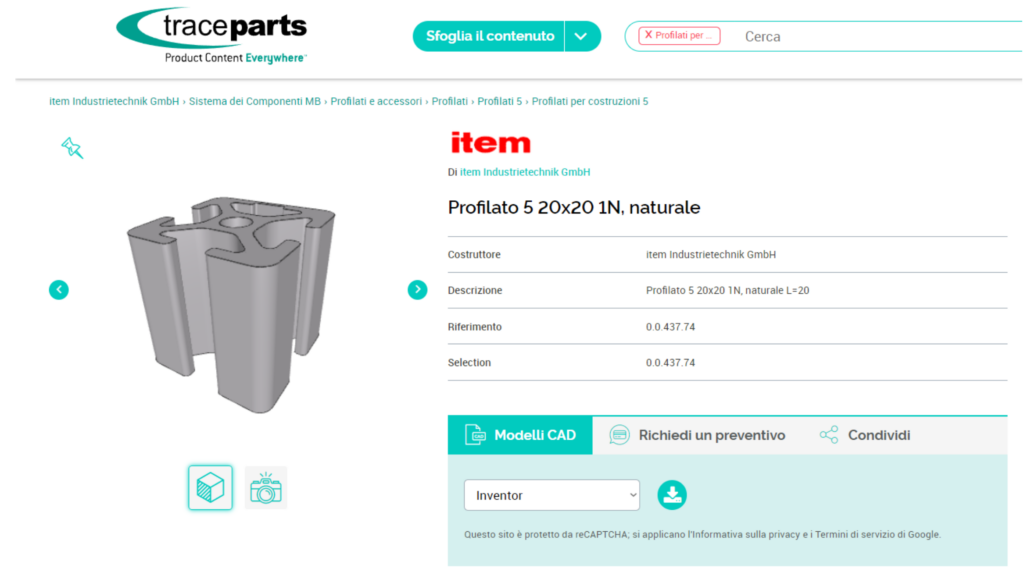
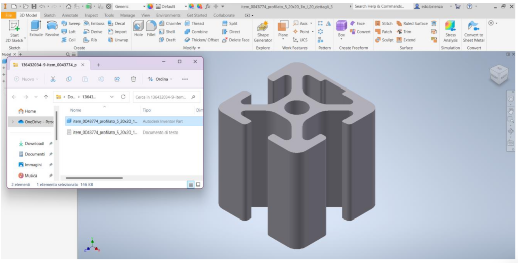
Depending on the component, there may be different sizes of the same component available.
Edoardo Brienza
Lascia un commento